
Call Support 24/7
+86-28-68724242

product
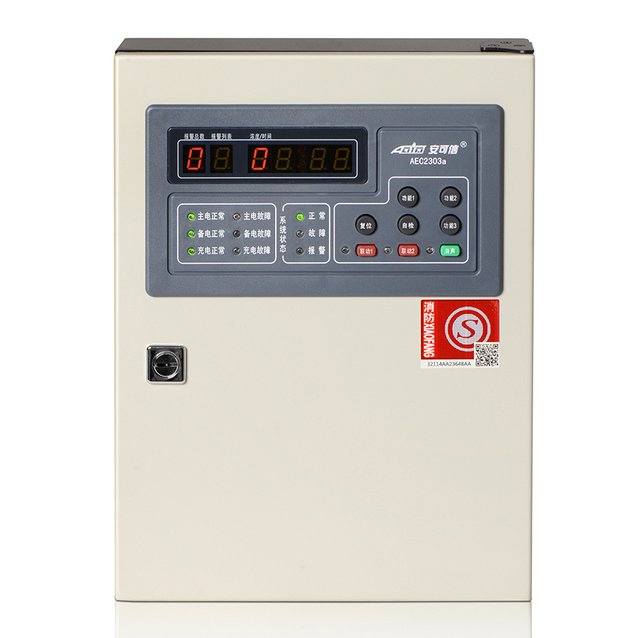
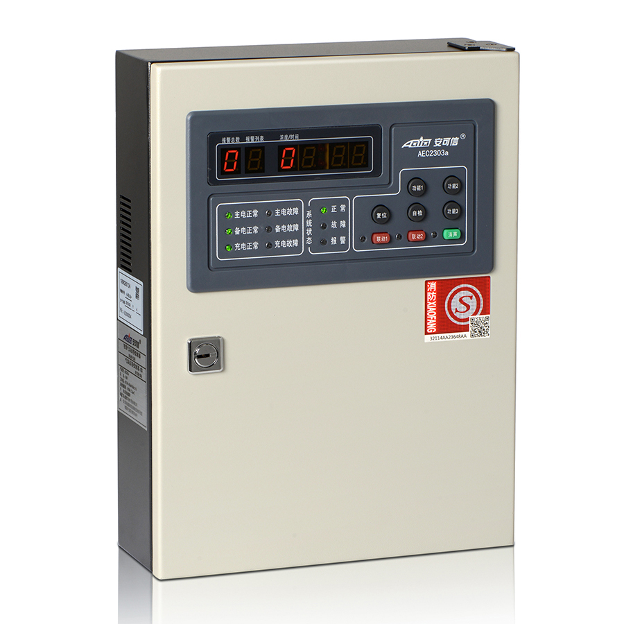
Panel Gas Detector Gas Alarm Controller AEC2303a – Action
Short Description:


ACTION gas detectors are OEM & ODM supported and true mature devices, long-tested in millions of projects domestic and overseas since 1998! Don't hesitant to leave your any inquiry here!
Panel Gas Detector Gas Alarm Controller AEC2303a – Action Detail:
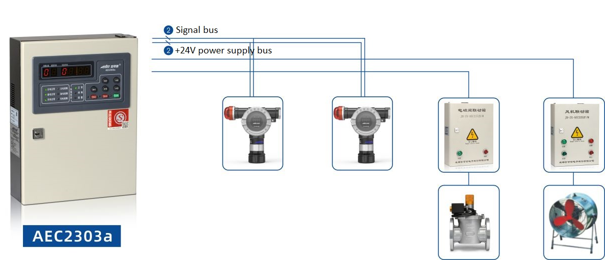
Technical Specifications
| Operating voltage | AC176V~AC264V (50Hz±1%) |
| Power consumption | ≤10W (excluding supporting equipment) |
| Environmental condition for operating | temperature-10℃~+50℃, relative humidity≤93%RH |
| Signal transmission | four-bus system (S1, S2, +24V and GND) |
| Signal transmission distance | 1500m (2.5mm2) |
| Types of gas detected | %LEL |
| Capacity | total number of detectors and input modules≤4 |
| Adaptive equipment | gas detectors GT-AEC2331a, GT-AEC2232a, GT-AEC2232bX/A |
| Input module | JB-MK-AEC2241 (d) |
| Fan linkage boxes | JB-ZX-AEC2252F |
| Solenoid valve linkage boxes | JB-ZX-AEC2252B |
| Output | two sets of relay contact signals, with the capacity of3A/DC24V or 1A/AC220V RS485Bus communication interface (standard MODBUS protocol) |
| Alarm setting | low alarm and high alarm |
| Alarming mode | audible-visual alarm |
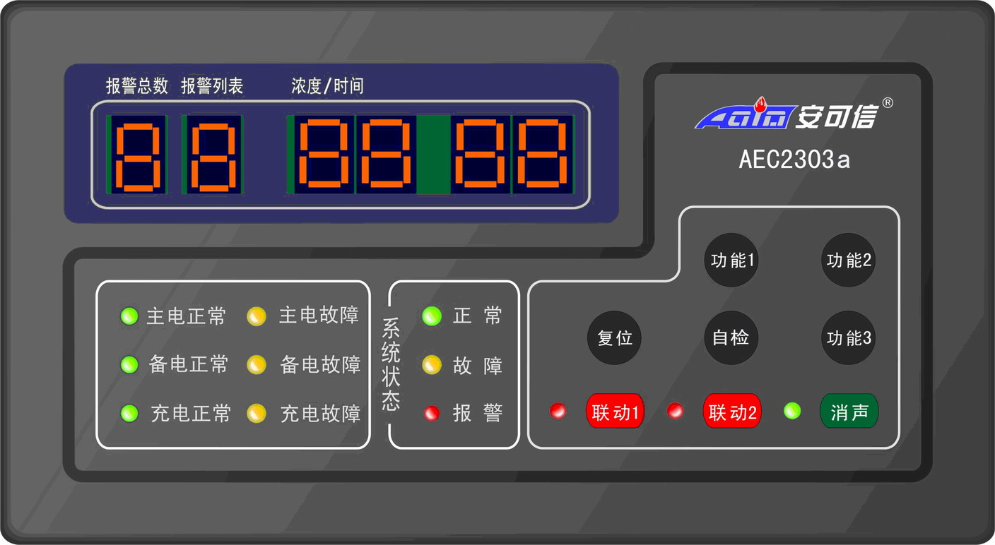
| Display mode | nixie tube |
| Boundary dimensions(length ×width ×thickness) | 320mm×240mm×90mm |
| Mounting mode | wall-mounted |
| Standby power supply | DC12V /1.3Ah ×2 |
Major Features
● Bus signal transmission, strong system anti-interference capability, cost-efficient wiring, convenient and efficient installation;
● Real-time gas concentration (%LEL) monitoring interface or time display interface for user’s choice;
● One-button start for simple and convenient system commissioning;
● Freely setting the alarm values of the two alarming levels in the full-scale range;
● Automatic calibration, and automatic tracing of sensor ageing;
● Automatically monitoring failure; correctly showing the failure location and type;
● Two sets of programmable internal linkage output modules and two programmable emergency buttons to automatically or manually control external equipment;
● Strong memory: historical records of the latest 999 alarming records, 100 failure records and 100 startup/shutdown records, which will not be lost in case of power failure;
● RS485 bus communication (standard MODBUS protocol) interface to realize communication with the host control system and networking with the fire and gas network system, to improve system integration.
Structure
1. Side lock
2. Cover
3. Horn
4. Bus connection terminal
5. RS485 bus communication interface
6. Relay connection terminal
7. Bottom box
8. Incoming hole
9. Grounding terminal
10. Power supply terminal
11. Switch of main power supply
12. Switch of standby power supply
13. Switch power supply
14. Standby power supply
15. Control panel

Panel Marks And Mounting Instructions

● Make 4 mounting holes (hole depth: ≥40mm) in a wall as per the requirements for bottom board mounting holes (hole symbols 1-4);
● Insert a plastic expansion bolt into each mounting hole;
● Fix the bottom board onto the wall, and fasten it onto the expansion bolts with 4 self-tapping screws (ST3.5×32);
● Hang the welding hanging parts on the back of the controller onto location A at the bottom board to complete mounting of the controller.
Panel Marks And Mounting Instructions
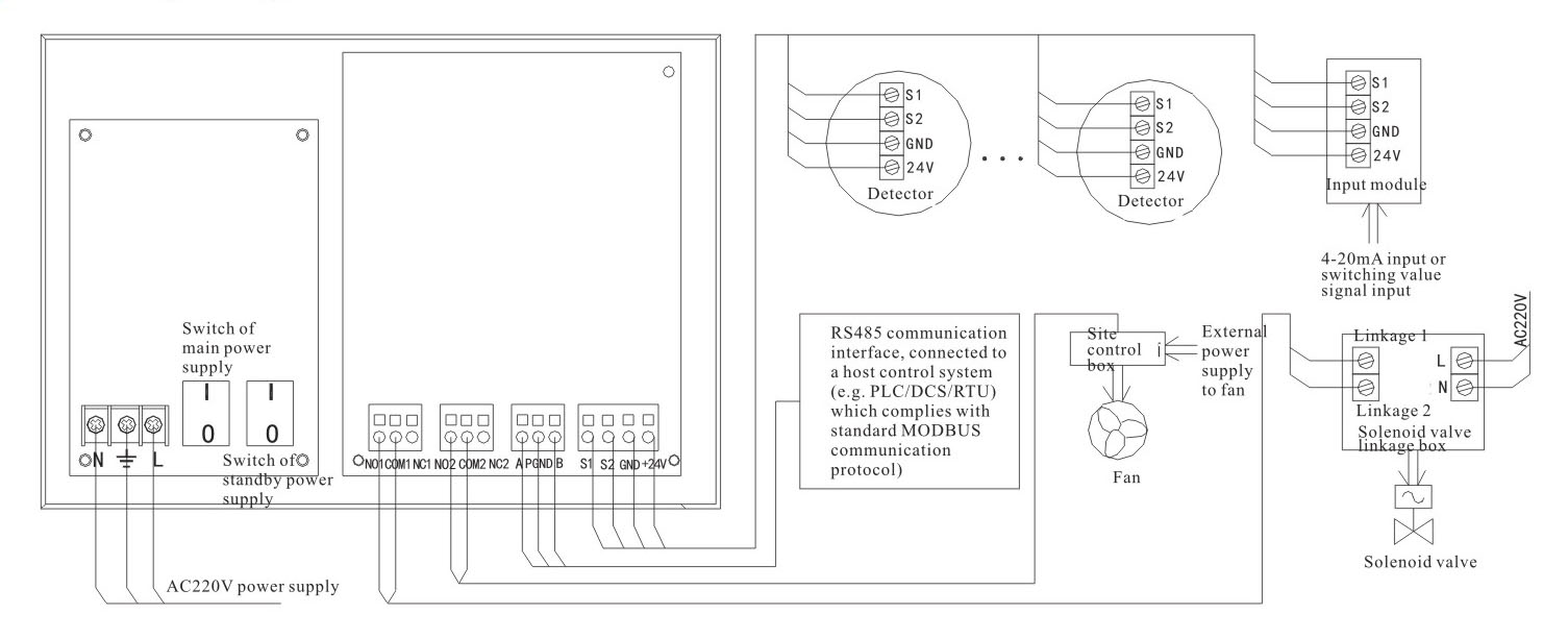
L,and N: AC220V power supply terminals
NC (normally closed), COM (Common) and NO (normally open): (2 sets) output terminals for relay external control signals output terminals
S1, S2, GND and +24V: system bus connection terminals
A, PGND and B: RS485 communication interface connection terminals
Product detail pictures:
Related Product Guide:
We are convinced that with joint endeavours, the small business between us will bring us mutual benefits. We could assure you products quality and competitive selling price for Panel Gas Detector Gas Alarm Controller AEC2303a – Action , The product will supply to all over the world, such as: Jamaica, belarus, Greece, We would very much welcome an opportunity to do business with you and have pleasure in attaching further details of our products. Excellent quality, competitive prices,punctual delivery and dependable service can be guaranteed.
 By Heather from Ottawa - 2018.10.31 10:02
The manufacturer gave us a big discount under the premise of ensuring the quality of products, thank you very much, we will select this company again.
By Eleanore from Hungary - 2018.07.26 16:51