
Call Support 24/7
+86-28-68724242

product
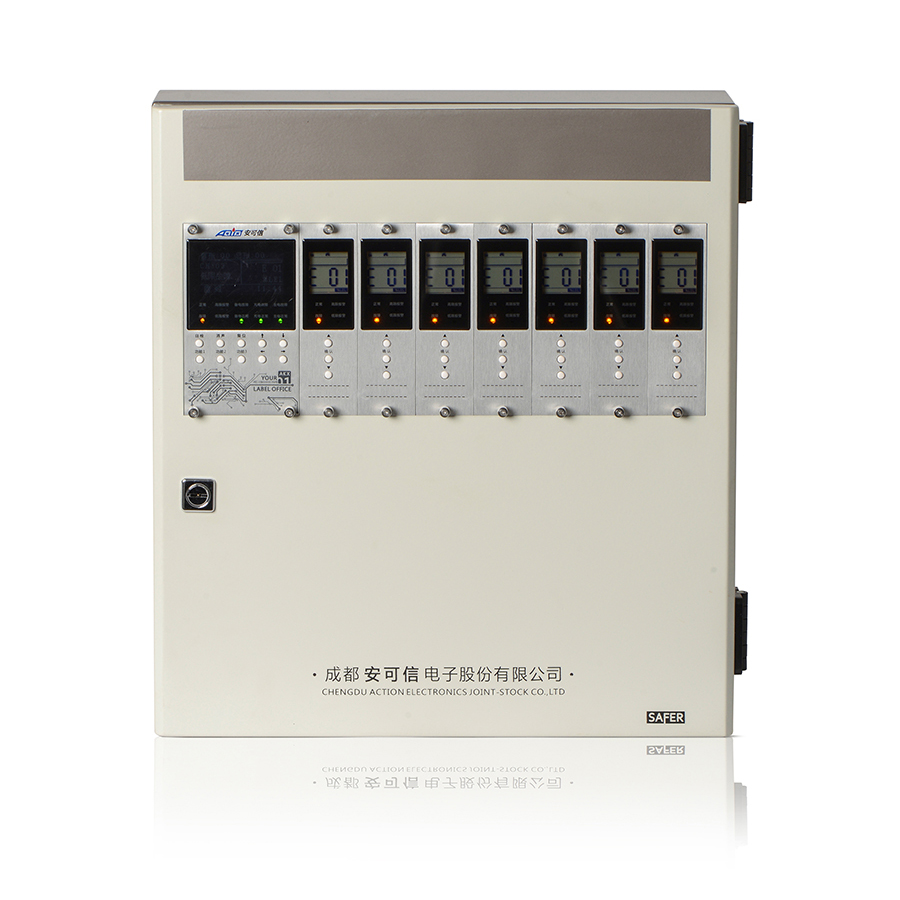


AEC2392a-BS/BM Gas Controller
Short Description:
Three-wire system signal transmission; wall-mounted casing; anti-RFI/EMI interference;
This product has a beautiful appearance and a portable size, several devices can be wall-mounted together;
The master control card and channel cards are set separately and with synchronous display function. The master control card has a Large LCD Chinese display screen, can be Chinese menu operation, display and operate faster and easier;
Channel cards’ multiple output types are applicable to linkage of on-site external control devices. By using standard MODBUS communication protocol, RS485 communication function can communicate with the host computer (e.g. DCS/PLC/EDS/RTU, etc.);
ACTION gas detectors are OEM & ODM supported and true mature devices, long-tested in millions of projects domestic and overseas since 1998! Don't hesitant to leave your any inquiry here!
Technical Specifications
|
Item |
Data |
|
Configuration |
One master control card, seven channel cards and one wall-mounted casing(AEC2392a-BS) |
|
One master control card, fifteen channel cards and one wall-mounted casing(AEC2392a-BM) |
|
|
Boundary dimension of the rack |
Wall-mounted casing (length × width x height: 426mm×392mm×117mm) (AEC2392a-BS) |
|
Wall-mounted casing (length × width x height: 430mm×565mm×145mm) (AEC2392a-BM) |
|
Item |
Master control card |
Channel card |
|
Operating power supply |
DC24V±6V |
|
|
Types of gas detected |
%LEL/%VOL/ppm |
|
|
Range |
(0~100)%LEL, (0~100)%VOL, (0~9999)ppm |
|
|
Value indication error |
±5%FS |
|
|
Operating mode |
Connected to channel cards or working independently |
Connected to the master control card or working independently |
|
Capacity |
8(16), to connect seven channel cards; the master control card can connect one set of 4-20mA standard current signal |
One channel card connects one 4-20mA transmitter |
|
Power consumption |
3W |
1W/channel card |
|
Input signals |
Connect to (4~20)mA standard current signals or passive switching value signals locally or via a channel card |
4~20mA standard current signals or passive switching value signals |
|
Output signals |
1. RS485 bus communication signal (standard MODBUS protocol);2. Signals of 3 sets of relays (relays 1, 2 and 3); contact capacity: AC250V/10A or DC30V/10A. | One channel card can output:Signals of 3 sets of relays (high alarm, low alarm and failure); contact capacity: AC250V/10A or DC30V/10A |
|
Environmental condition for operating |
Temperature: 0℃~+40℃; relative humidity: ≤93%; atmospheric pressure: 86kPa~106kPa |
|
|
Alarming mode |
LED visual alarm |
|
|
Display mode |
OLCD Chinese display |
LCD segment code display |
|
Switch power supply |
AC176V~AC264V (50Hz±0.5Hz); under voltage test point 170V±10V; main power supply’s max. working current: 1A |
|
|
External standby power supply |
DC12V /4Ah×2 lead-acid battery (AEC2392a-BS) |
|
|
DC12V /7Ah×2 lead-acid battery (AEC2392a-BM) |
||
| Mounting mode |
Wall-mounted |
|
Note: The default system input signals are (4~20)mA standard signals; when the input signal is a passive switching value signal, the default signal is a passive normally-open signal; if a user requires that the default signal should be a passive normally-close signal under such case, please specify when ordering.
Major Features
● Three-wire system signal transmission; wall-mounted casing; anti-RFI/EMI interference;
● This product has a beautiful appearance and a portable size, several devices can be wall-mounted together;
● The master control card and channel cards are set separately but have a function of synchronous display. With a large LCD Chinese display screen, the master control card can realize Chinese menu operation as well as faster and easier display and operation;
● Channel cards’ multiple output types are applicable to linkage of on-site external control devices. By using standard MODBUS communication protocol, RS485 communication function can communicate with the host computer (e.g. DCS/PLC/EDS/RTU, etc.);
● Channel cards can receive 4-20mA signal or switching value signal input and be connected with various devices, including combustible gas detectors, toxic and hazardous gas detectors, oxygen detectors, flame detectors, smoke/heat detectors and manual alarming buttons, etc;
● Save the latest 999 alarming records, 999 failure records and 100 startup/shutdown records for check, which will not be lost in case of power failure;
● Channel cards have a three-color backlight LCD, which can indicate normal, failure and alarming status clearly;
● The master control card integrates the functions of the power supply card and the one-circuit channel card. All channels can be equipped with a HART communication module, showing a strong function.
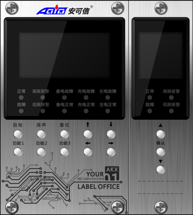
Control panel
The control panel contains the display interfaces and operating interfaces of the master control card and channel cards, including the display screen, the LED status indicator, the alarm buzzer (installed inside the master control card) and operating keys. The master control card has ten operating keys while a channel card has three ones (see the following diagram):
Mounting
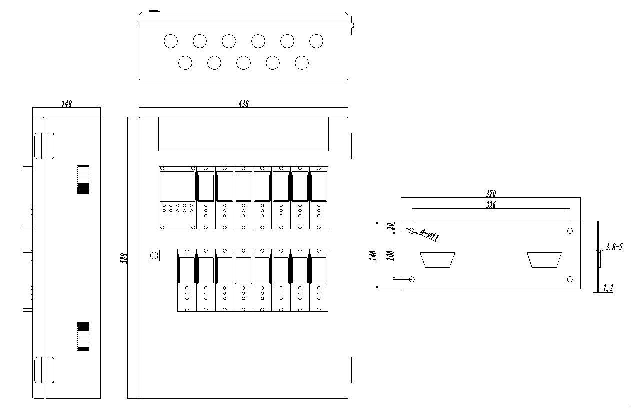
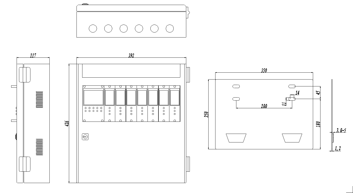
● Make 4 or 6 mounting holes (hole depth: ≥40mm) in a wall according to the requirements for the size among mounting holes (hole symbols 1 – 6) for mounting the hanging plate;
● Insert a plastic expansion bolt into each mounting hole;
● Fix the hanging plate onto the wall and fasten it onto the expansion bolts with 4 or 6 self-tapping screws (ST4.2×25);
● Hang the hanging parts at the bottom of the controller onto location A at the bottom board to complete mounting of the controller.
External interface
The master control card connects 9 circuits of channel cards. Each channel card collects 4-20mA multi-line or passive switching value signal output communication equipment, such as GT-AEC2232bX, GQ-AEC2232bX, GT-AEC2232aT, AEC2338, GQ-AEC2232bX-P, AEC2338-D detectors and flame detectors. It can also connect other 4-20mA output transmitters. Two sets of built-in modules of the master control card can realize remote linkage of external devices (on-site sound and light, solenoid valves and fans, etc.). External devices (e.g. on-site sound and light) can also be controlled through three sets of relay signal output terminals provided by each channel card. Remote communication with the host system can be done through the RS485 communication interface so that the host system can monitor AEC2392a-BS/AEC2392a-BM gas detection systems in several areas intensively.
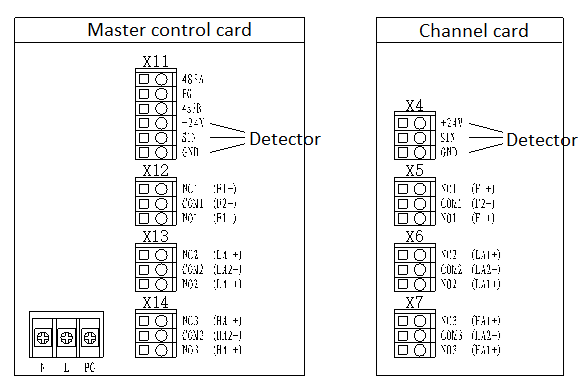
Master control card:
485A and 485B: RS485 communication interface connection terminals
L, PG and N: AC220V power supply terminals
NC*(normally closed), COM* (common) and NO* (normally open): (3 sets) output terminals for relay external control signals output terminals
V+, SIN and GND: input terminals for 4~20mA or passive switching value signals
Channel card:
NC*(normally closed), COM* (common) and NO* (normally open): (3 sets) output terminals for relay external control signals output terminals
24V, SIN and GND: input terminals for 4~20mA or passive switching value signals
When the signal connected is a passive switching value signal, the two ends of the signal are connected to 4~20mA (IN) and +24V. If DC24V power will be supplied to the equipment connected, the wiring is as shown in the system configuration diagram.
Internal terminal:
CAH, CAL, VSS and 24V: connection terminals for internal communication (connected in the factory)
Notes: (1) The maximum allowable wire diameter for connection terminals is 2.5mm2. (2)Factory default of the master control card’s relay output is passive switching value signal.